Hall Sensor FTMS Server
I’ve made quite a bit of progress on my FTMS server for my bike. I’ve settled on a hardware configuration and completed the firmware implementation. Now I just need to solder it together and 3d print an enclosure! In the process I’ve learned a lot about Arduino, C, C++, and Hall sensors. For those that haven’t worked with Hall sensors before, they detect electromagnetic fields and generate either an analog or digital signal based on the magnitude of their force.
The ESP32 that I’m using actually has an onboard Hall sensor, but I decided to use an external sensor instead, for two reasons. The first is that the ESP32 sensor doesn’t support digital input, only analog. There’s a quite a bit of drift between separate peaks and troughs, so it was simpler to just use an on (magnetic detected)/ off (magnetic absent) digital signal for my tachometer logic. The second was that by using external hall sensor I could force myself to become better acquainted with the ESP32s GPIO (General Purpose Input/Output) pins.
There are few different ways that I could have processed the hall sensor signal. One approach is to use a pulse counter (PCNT). You can use PCNT hardware to count the number of pulses from a particular input. The PCNT stores the pulse count in a register, from which you can read the current count and then clear it. This can be more reliable than trying to count the pulses manually. I initially started with this approach but found the hall sensor signal to be too noisy for this to work reliably.
Another approach is to use Arduino’s TIMG API to set an interrupt for your pin. TIMG will contain the number of clock ticks since the last interrupt and clear the ticks after the interrupt has occurred. When using interrupt service routines, you need to make sure that you lock the memory for variables both in the ISR and the loop(). If the memory location is accessed in two places at once it will throw a runtime exception. To lock the memory you need to declare a mux variable like below:
portMUX_TYPE revMux = portMUX_INITIALIZER_UNLOCKED;
and then lock using
portENTER_CRITICAL_ISR(&revMux);
and unlock using
portEXIT_CRITICAL_ISR(&revMux);
I ultimately decided against this approach for the same reason as the first; the signal was just too noisy to use without receiving a lot of false positives.
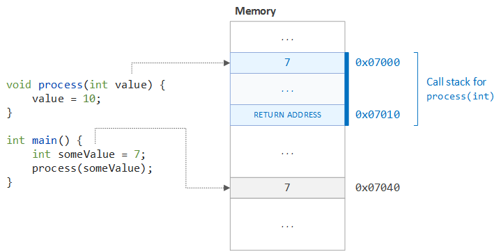
I had to look up the meaning of the “&” operator shown above because it’s not normally used in higher-level languages like Swift and Kotlin. Its purpose is to retrieve the actual memory address of a prefixed variable. The “*” operator is similar in that it provides a pointer to a variable’s memory address. A pointer provides an additional layer of safety above direct memory address access in that they can be set to null. This prevents you from accessing unallocated or garbage memory. In C and C++ programming you can accidently corrupt memory, causing undefined behavior when accessing other, unrelated variables. The best way to troubleshoot these issues is by using a memory profiler like this. Speaking of memory, both C and C++ by default are pass-by-value, not pass by reference like a lot of higher level languages. I filched an diagram of pass-by-value from the excellent Java blog Dzone, shown below:
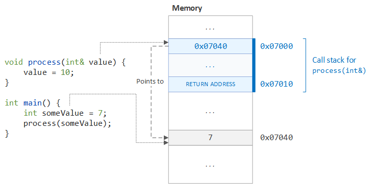
You can modify function parameter syntax to pass references instead of values by explicitly using the “&” operator as shown below (graphic also from Dzone):
For troubleshooting timing issues in the Arduino IDE you can use the `micros()` function. This returns the current time in microseconds. This in turn allows you to detect minute differences in execution times.
Neither C or C++ have the concept of Bytes or Byte Arrays. Instead you should use uint8_t from stdint.h. Arduino, which is a superset of C++, does have bytes and byte arrays however. As to the arrangement of the bytes, Arduino uses the “little-endian” system whereas ARM architecture uses the “big-endian” system. You can swap the byte order of an int with the standard function htonl() - which stands for Host TO Network Long (32 bit). There is also htons() - which is the same as htonl except its for Short 16 bit values. To reverse these operations you would use ntohl() or ntohs().
If you write your own bit reversal algorithm, the most efficient means in terms of memory and speed is to to use a nibble lookup table. It is O(1) lookup time, but only occupies a lookup array of 4 bits for each of the 16 indexes, for a total of 8 bytes. I’ve included an example below:
/*lookup reverse of bottom nibble
  |       + grab bottom nibble
  |       |        + move bottom result into top nibble
  |       |        |     + combine the bottom and top results
  |       |        |     | + lookup reverse of top nibble
  |       |        |     | |       + grab top nibble
  V       V        V     V V       V
 (lookup[n&0b1111] << 4) | lookup[n>>4]
*/
static unsigned char lookup[16] = {
0x0, 0x8, 0x4, 0xc, 0x2, 0xa, 0x6, 0xe,
0x1, 0x9, 0x5, 0xd, 0x3, 0xb, 0x7, 0xf, };
byte reverseBits(byte n)
{     return (lookup[n&0b1111] << 4) | lookup[n>>4];
}
If you’re using bits to indicate flags you will need to reverse the bit and byte order before transmitting. For actual numerical values you only need to reverse the the byte order. If you don’t expect to interpret the bytes on the ESP32, you can just encode the bytes in big-endian order with no issue however. This saves compute time because it means you don’t have to reverse the bytes before transmitting. When it comes to actually transmitting the values as bytes I found the following logic extraordinarily useful:
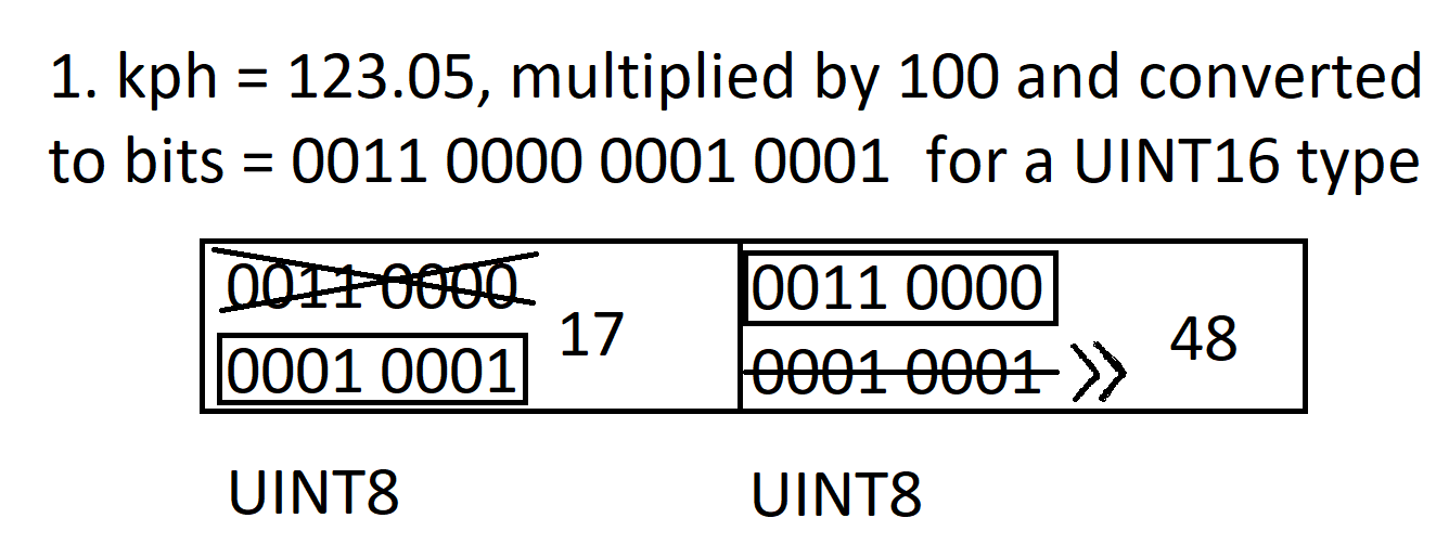
uint16_t transmittedKph     = (uint16_t) (kph * 100);         //(0.01 resolution)
byte bikeData[2]={(uint8_t)transmittedKph, (uint8_t)(transmittedKph >> 8)}
The example above shows how the speed value, which according to the Indoor Bike Data Characteristic needs to be an unsigned 16 bit integer, can be split up across two bytes. The first byte is captured by casting to an unsigned 8 bit integer, which truncates the leading bits. The second byte is shifted right 8 bits and then cast, truncating the trailing bits. The end effect is that the 16 bit integer is now split between two separate 8 bit bytes keeping the array format uniform. This is demonstrated below with a placeholder kph of 123.05:
The final lesson that I learned was that even though the ATT_MTU (ATTribute Maximum Transmission Unit) for BLE is 23 bytes, android by default only captures the first 20 bytes. For this reason I had to limit the number of values that I sent to just instantaneous speed, average speed, instantaneous cadence, total distance, instantaneous power, expended energy, and elapsed time.
comments powered by Disqus